M&MRefrigeration, Inc.
Controller Overview
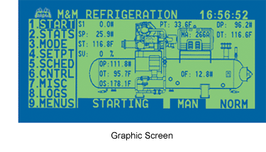
The M&M Compressor Control System is an advanced microcontroller that has been specifically developed to provide the industry’s most extensive compressor control flexibility and safety. It is easy to use with no prior computer knowledge being necessary. All information is clearly presented on three types of display screens:
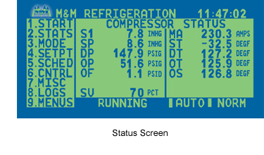 S1 Suction Pressure Setpoint (four available)
SP Actual Suction Pressure
DP Discharge Pressure
OP Oil Pressure (above discharge pressure)
OF Oil Filter Pressure Drop
SV Slide Valve Position
 MA Motor Amps
ST Suction Temperature
DT Discharge Temperature
OT Oil Temperature (into the compressor)
OS Oil Separator Temperature
The Main Status Screen also displays:
Operation Mode
(Local, Manual, Automatic, Remote, Auto Remote, Sequenced)
Operation Status
(Running, Starting, Stopped, Alarm, etc.)
Alarm or Failure Message
(62 possible messages)
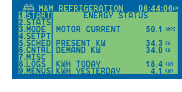 Energy Status Screen displays real-time values of the following useful energy data:
Motor Current
Present kW (instantaneous demand)
Demand kW (average demand calculated over the
last 15 minutes)
Today’s kWh (total energy consumed since midnight)
Yesterday’s kWh (total energy consumed on the previous day)
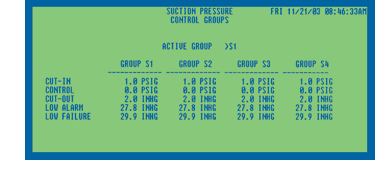 Control Setpoints Screen permits the operator to enter up to four suction pressure control setpoints, with corresponding cut-in and cut-out pressure selections. In addition, the operator can choose to operate the compressor solely on either setpoint, or to let the compressor automatically select the setpoint from a pre-determined, selectable suction pressure setpoint schedule.
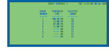 Setpoint Scheduling Screens provide tremendous flexibility of operation between the four available suction pressure setpoints. The microcontroller can be programmed for as many as eight setpoint changes per day, with up to seven different daily schedules. This valuable feature can save energy in plants operating on time-of-day electric rates, or in plants where cooling loads vary on an hourly and/or daily basis
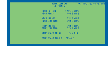 Operating, Alarm and Failure Setpoints Screens provide operator adjustable entries for key compressor parameters which when exceeded will trigger an alarm or shut down the compressor. A description of the alarm or failure will be shown on the Active Alarm and Failures Screen, and will also be stored in the Operation Log and in the Alarm or Failure History. These screens also contain selectable parameters to establish a gradual, controlled startup and loading of the screw compressor. Capacity, discharge pressure and motor amps are allowed to gradually increase during the startup period by controlling the movement of the slide valve in response to changes in these parameters. This feature eliminates possible current spikes that can create an excessive demand charge during startup.
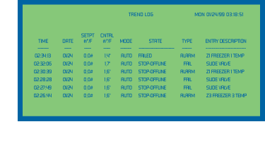 Operation Log records all data from the status screen for the past one hour, in 30 second intervals. In the event of an alarm or failure, an entry is recorded at the time of the malfunction, and the offending parameter is identified. Provision is also made for auxiliary input safeties, motor starter failure, bad sensor detection and faulty startup sequence check.
 Trend Log provides the same information as the operation log by recording the last 200 sets of compressor operating parameters (i.e., main status screens) at a time interval selected by the operator (typically every 15 minutes).
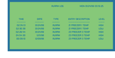 Alarm, Failure and User Logs displays the last 50 messages, irrespective of time of occurrence. These messages include date and time of occurrence and a description of the alarm or failure. The user log records user number entries by date and time. These screens are of tremendous value in identifying chronic problems or for basic troubleshooting.
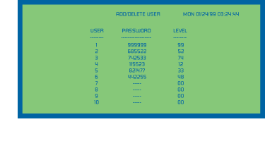 Password Menu Screen permits the operator to assign passwords for up to 10 control users. In addition, there can be as many as 99 different levels of password access, ranging from “observe only” to complete access for making data entries on all screens. Access to the password schedule screen requires the highest access level password. This extensive password system ensures complete security control and flexibility.
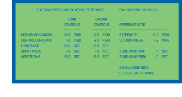 Adjust Controls Screen provides a means of adjusting capacity control (slide valve movement) sensitivity.Operator selectable entries for normal bandwidth (suction pressure differential), control deadband, update time, shortest slide valve pulse, and longest slide valve pulse are provided. In addition, pertinent real-time control data is displayed to facilitate control adjustments.