M&M Refrigeration, Inc.
Refrigeration Pressure Vessels
Standard Vertical High Pressure Receiver
· Standard Horizontal High Pressure Receiver
· Standard Vertical Accumulator
Standard Vertical Intercooler
· Standard Single Flow Horizontal Surge Drum
· Standard Dual Flow Horizontal Surge Drum
Standard Horizontal Recirculator Bare Vessel
· Standard Vertical Recirculator Bare Vessel
· Back
to Main Page
Standard Vertical Recirculator Bare Vessel
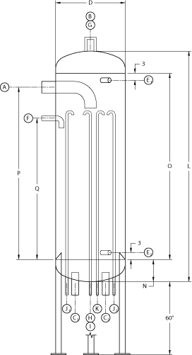 |
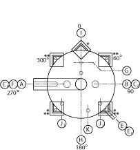 * 24" vessels have 3 legs (0 - 120 - 240) ** 30" and larger have 4 legs (45 - 135 - 225 - 315) |
| LEGEND | ||||
| Nozzle | Descripition | Connection | ||
| A | Wet Return | Stub | ||
| B | Gas Outlet | Stub | ||
| C | Pump Suction | Stub | ||
| E | Float Column | Stub | ||
| F | Liquid Makeup | Stub | ||
| G | Relief | Coupling | ||
| H | Oil Drain | Stub | ||
| I | Oil Pot Vent | Coupling | ||
| J | Volute Vent | Stub | ||
| K | Liquid By-Pass | Stub | ||
| M | Pump Bleed | Stub | ||
| DIMENSIONS | ||||||||||||||||||
| Model Number | A | B | C | D | E | F | G | H | I | J | K | L | N | O | P | Q | Surge Vol Cu. Ft. | Wt. (Lb) |
| VRC-24-112 | 5 | 4 | 2-1/2" | 24" | 1-1/2" | 2" | 3/4" | 2" | 3/4" | 3/4" | 1" | 112-1/2" | 8-1/4" | 96" | 90" | 74" | 14.99 | 1200 |
| VRC-30-115 | 6 | 5 | 3" | 30" | 1-1/2" | 2" | 3/4" | 2" | 3/4" | 3/4" | 1-1/4" | 115-1/2" | 9-3/4" | 96" | 90" | 74" | 24.11 | 1475 |
| VRC-36-118 | 6 | 6 | 4" | 36" | 1-1/2" | 2" | 3/4" | 2" | 3/4" | 3/4" | 1-1/4" | 118-1/2" | 11-1/4" | 96" | 90" | 74" | 35.08 | 2325 |
| VRC-42-145 | 8 | 6 | 4" | 42" | 1-1/2" | 2-1/2" | 3/4" | 2" | 3/4" | 3/4" | 1-1/2" | 145-1/2" | 12-3/4" | 120" | 112" | 94" | 61.89 | 3200 |
| VRC-48-148 | 8 | 8 | 5" | 48" | 1-1/2" | 3" | 3/4" | 2" | 3/4" | 3/4" | 1-1/2" | 148-1/2" | 14-1/4" | 120" | 112" | 94" | 81.33 | 4615 |
| VRC-54-152 | 10 | 8 | 5" | 54" | 1-1/2" | 3" | 3/4" | 2" | 3/4" | 3/4" | 1-1/2" | 152" | 16" | 120" | 110" | 91" | 97.03 | 4420 |
| VRC-60-155 | 10 | 8 | 5" | 60 | 1-1/2" | 3" | 3/4" | 2" | 3/4" | 3/4" | 1-1/2" | 155" | 17-1/2" | 120" | 110" | 91" | 118.66 | 6140 |
| VRC-72-161 | 12 | 10 | 6" | 72" | 1-1/2" | 4" | 1" | 2" | 3/4" | 3/4" | 1-1/2" | 161" | 20-1/2" | 120" | 108" | 88" | 161.53 | 9210 |
| VRC-84-167 | 12 | 10 | 8" | 84" | 1-1/2" | 4" | 1" | 2" | 3/4" | 3/4" | 2" | 167" | 23-1/2" | 120" | 108" | 88" | 219.64 | 11175 |
| VRC-96-172 | 14 | 12 | 8" | 96" | 1-1/2" | 5" | 1" | 2" | 3/4" | 3/4" | 2" | 172-1/2" | 26-1/4" | 120" | 106" | 84" | 266.47 | 15990 |
Notes:
All dimensions and Nozzle sizes are given in inches.
Please consult factory for certified drawings.
Surge volume is the amount of area between normal operating level and high level cutout.
24" thru 48" vessels are designed for 300# DWP -40 +200 Design Temp Per ASME Section VIII, Division 1
54" and larger vessels are designed for 250# DWP -40 +200 Design Temp Per ASME Section VIII, Division 1
| VERTICAL RECIRCULATOR CAPACITIES - OPERATING TEMPERATURE | |||||||||||
| Model Number | TWO STAGE | SINGLE STAGE | |||||||||
| -50 | -40 | -30 | -20 | -20 | -10 | 0 | +10 | +20 | +30 | +40 | |
| VRC-24-112 | 51.9 | 64.3 | 77.8 | 92.1 | 80.1 | 92.7 | 105 | 120 | 134 | 147 | 149 |
| VRC-30-115 | 82.1 | 102 | 123 | 145 | 126 | 147 | 166 | 189 | 213 | 234 | 251 |
| VRC-36-118 | 117 | 146 | 176 | 209 | 181 | 210 | 237 | 271 | 305 | 334 | 359 |
| VRC-42-145 | 161 | 200 | 242 | 287 | 249 | 288 | 326 | 372 | 418 | 459 | 492 |
| VRC-48-148 | 212 | 263 | 318 | 376 | 327 | 379 | 428 | 490 | 549 | 603 | 647 |
| VRC-54-152 | 270 | 334 | 405 | 478 | 416 | 481 | 544 | 623 | 698 | 767 | 822 |
| VRC-60-155 | 334 | 414 | 501 | 593 | 516 | 597 | 674 | 771 | 865 | 950 | 1019 |
| VRC-72-161 | 481 | 595 | 720 | 853 | 741 | 858 | 969 | 1109 | 1244 | 1366 | 1465 |
| VRC-84-167 | 654 | 809 | 979 | 1159 | 1008 | 1167 | 1318 | 1508 | 1692 | 1858 | 1991 |
| VRC-96-172 | 855 | 1056 | 1278 | 1513 | 1315 | 1522 | 1720 | 1968 | 2208 | 2425 | 2601 |
Notes:
Capacities are given in tons of refrigeration. (R-717)
Two stage capacities are based on +35 deg. F liquid feed temperature.
Single stage capacities are based on +95 deg. F liquid feed temperature.
![]()